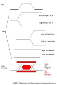
One of the methods used for checking signal quality is overlapping DATA signal with respect to a clock (clk).
Persistence must be ON for the overlapping of the DATA signal.
Jitter is the variation of the timing in the signal relative to the trigger (clk)
Jitter has many components such as but not limit to : Jitter Peak-Peak (JitterPP),Jitter RMS,Total Jitter( Jitter measurement are on the X of the eye diagram.
One of the instrument used for this type of measurement is Agilent’s 86100C DCA-J (J for jitter).
An additional test is the use of Mask Pattern
The Mask Pattern maybe established by the industry for the specific communication used or
it may be provided by the customer. Some Instrument will have the standard Mask in their library.
If not you may have to make you own Mask using line segments via your software development tool.
If your Jiitter seems excessive on a known good UUT — look at the trigger make sure it’s what you expect.
A source which creates random data signal is used to drive the (ex transceiver)
Here are some addition links to Eye Diagram and Agilent’s 86100C DCA-J
Agilent’s 86100C DCA-J http://cp.literature.agilent.com/litweb/pdf/5989-1146EN.pdf
Evaluation Engineering’s acticle: on Optical Transceiver : http://www.evaluationengineering.com/enews/2008_November/1108_optical.aspx
EDN’s info on eye diagram: http://www.edn.com/article/CA200381.html